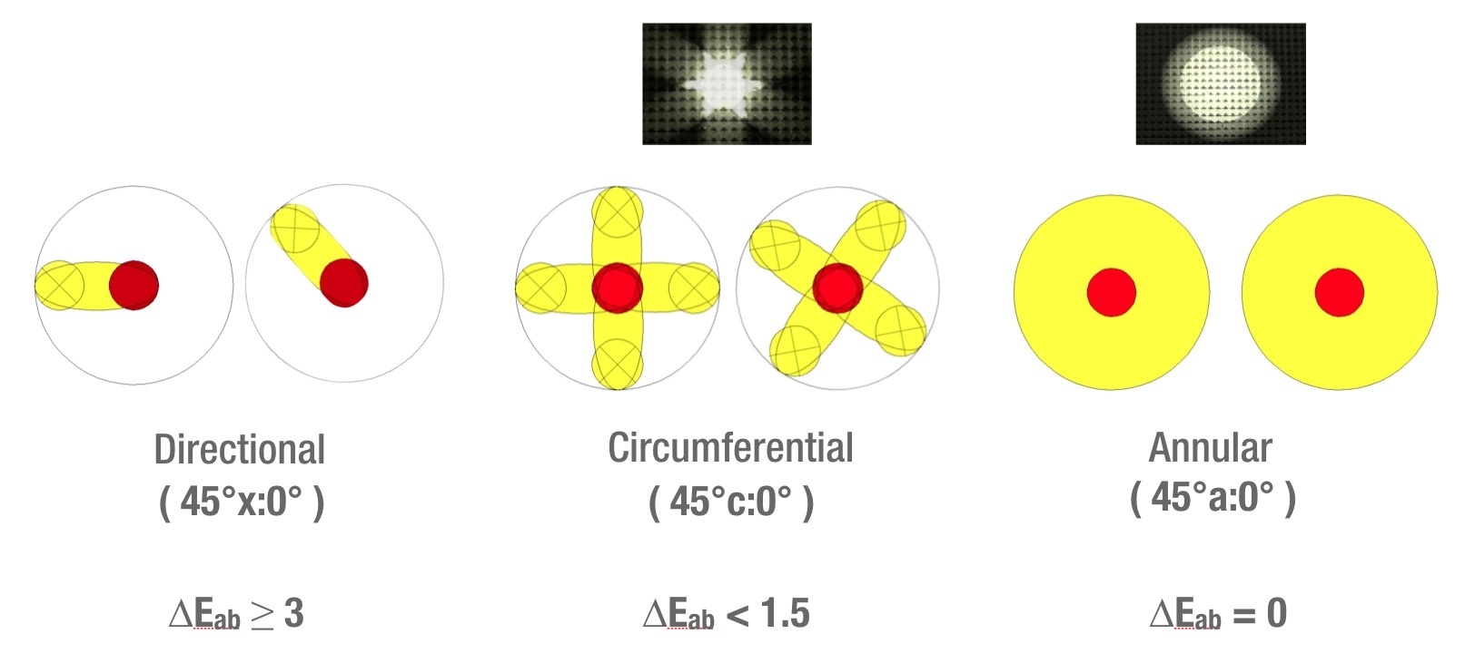
Figure 1: Illustration of different measurement geometries and the resulting directional effects in terms of colour differences.
ISO 13655:2017 Annex C reads:
“If, however, sensing and/or irradiation is limited to a single azimuthal angle, directional and texture effects are emphasized. These geometries are deprecated in ISO 5-4 and hence in this International Standard. They are known as “forty-five degrees directional: normal” and “normal: forty-five degrees directional”.
In other words when instruments with a directional geometry are used, results will be highly dependent on the measurement angle. When turning the spectrophotometer by some degree the same sample will give different readings. This effect gets stronger with increasing texture and on uncoated papers a colour difference of more than dE*ab = 3 can be experienced.
Question: How can users find out if a certain instrument conforms to the geometry requirements of ISO 13655?
Answer: The specification sheet of an instrument usually states the geometry. If this is not “45°a:0°” or “45°c:0°” (or the other way round) but only 45:0 most likely the requirements are not met. Also stating a conformance to DIN 5033 does not mean that the instrument conforms to ISO 13655. DIN 5033 simply describes all existing measurement geometries.
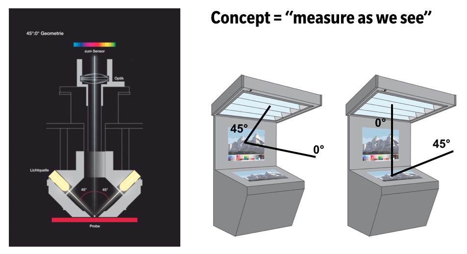
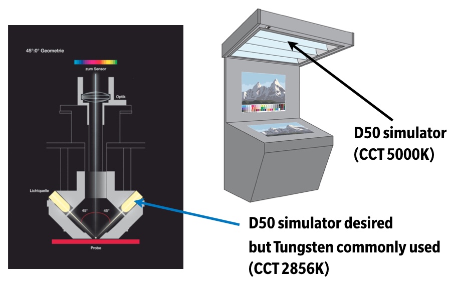
Figure 2: Illustration of the general concept for defining a new measurement method for ISO 13655.
Having met the prerequisites of measurement geometry, an instrument conforming to ISO 13655:2017 can comply with 4 different measurement modes. These modes were developed due to different needs and applications. They are called M0, M1, M2 and M3.
Figure 2: Illustration of the general concept for defining a new measurement mode for ISO 13655.
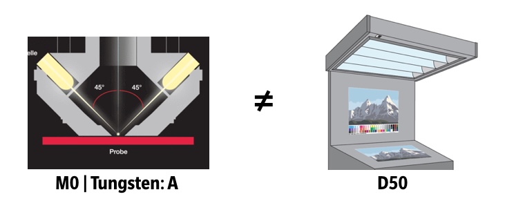
Figure 4: Simplified illustration of the M0 measurement mode when used in D50 lighting environment..
The following paragraphs will explain M2 and M3 before details regarding M1 which requires more explanation.
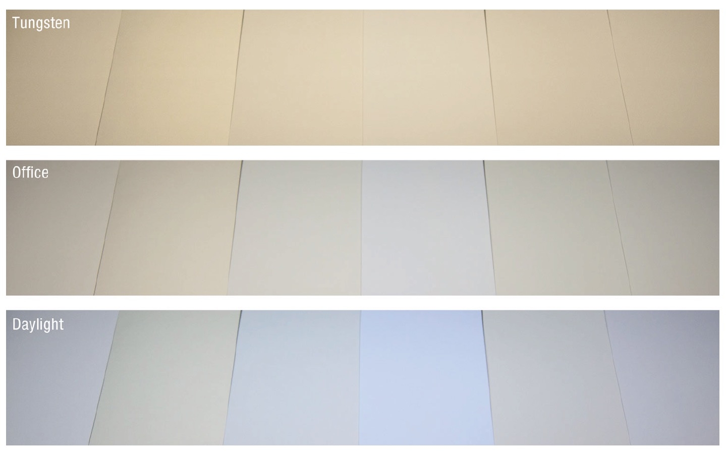
Figure 5: Typical production papers in environments with different levels of UV.
Optical brighteners do glow bluish depending on the UV-content in the viewing environment (and the light source of the measurement device). If a UV-filtered instrument leads to more pleasing results than an instrument with a tungsten lamp, the UV-content of the viewing environment is simply closer to UV-Cut than to the UV-content of a gas-filled tungsten lamp.
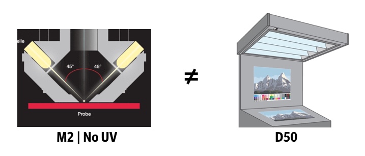
But most likely it is not UV-free (unless you work next to the Mona Lisa). Thus M2 is not the appropriate solution for most applications and it is only standardized to reflect UV-free viewing conditions.
The MYIRO instruments offer the choice of measurement mode M2. Here the definition of a UV-Cut filter from ISO 13655:2017 is met.
Take-home message:
M2 = UV-Cut. It’s only useful for UV-free environments.
Figure 6: Simplified illustration of the M2 measurement mode when used in D50 lighting environment.
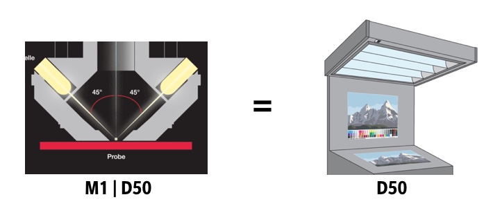
Figure 7: Simplified illustration of the M1 measurement mode when used in D50 lighting environment.
Method 1: Illuminant Match
M1 can be achieved by using a light source that fulfils the requirements of ISO 3664:2009. This simply means, that if you build a normlight into the spectrometer, it complies to M1 (but remember the prerequisite of geometry). This sounds simple but can not be achieved in practice.
The obvious choice of using the same light source as used in most viewing cabinets can’t be realized as these are mostly fluorescent lamps which cannot be built into a spectrophotometer. In addition they do not perfectly match CIE illuminant D50 (approximation within defined tolerances).
Another possibility for achieving D50 is to use a combination of different LEDs, which produce a D50 spectrum. In practice a problem occurs when trying to mimic the UV content of D50 as current LEDs are not capable of perfectly reproducing the UV content of D50.
The last presented technical solution for achieving D50 as physical illumination is to use filtered light sources to mimic the spectral power distribution of D50. The advantage is that with this technique a close match to D50 can be achieved. This should also provide correct measurements for samples that show fluorescence active in the visible wavelength area (few inks and toners do show this behaviour to some extent). The disadvantage is that the light source might not be stable in terms of its UV content and therefore reliability over time has to be questioned.
Furthermore we have to ask ourselves if perfect D50 is really the best solution to be used in a measurement device. Normally we do not have perfect D50 as a viewing condition but only a simulation within tolerance. So the theoretical benefits can hardly be transferred to practical usage. How this problem is overcome will be explained later in this document.
Method 2: UV Calculation
The second possibility to achieve conformance to measurement mode M1 is related to the nature of optical brighteners. Optical brighteners absorb UV energy and emit blue visible light. To measure the effect of an optical brightener it is perfectly sufficient to assure a correlation between brightener excitation during the measurement and in the desired viewing environment. This is described by means of the ratio between UV-content and visible content in ISO 13655:2017.
In other words: Make sure that during the measurement the brightener glows as bluish as in your desired viewing environment.
This can be achieved in different ways. In the available literature some methods are described. Two will be discussed in the following.
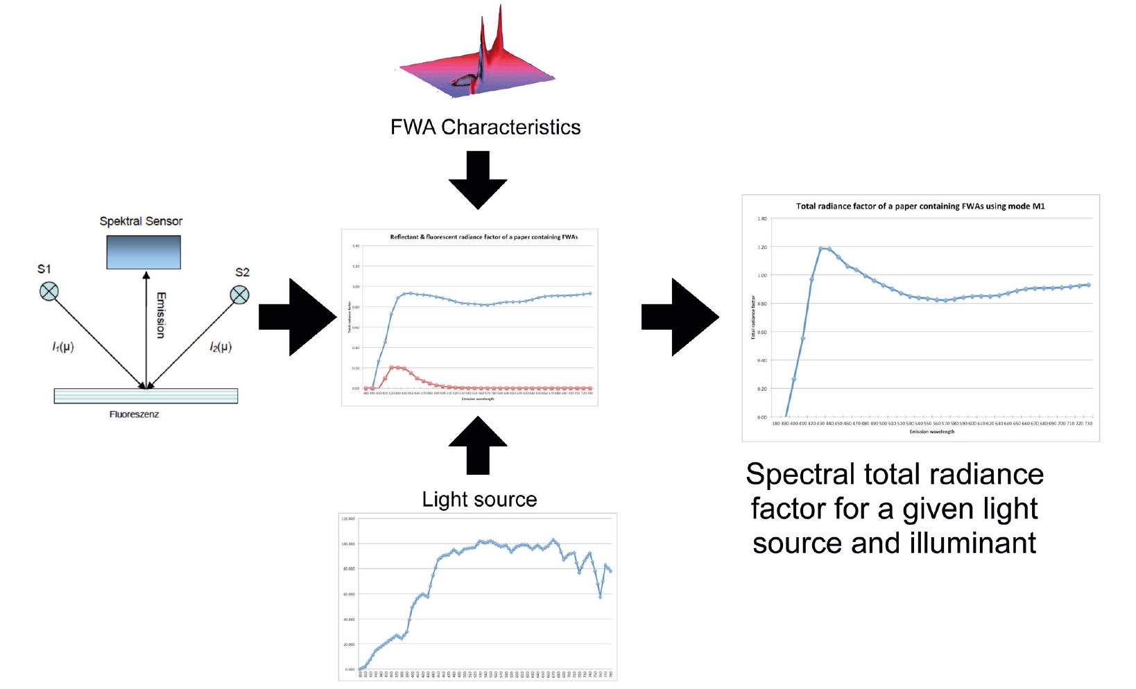
As discussed, an optical brightener absorbs UV energy and emits this energy as blue light. Should we like to measure the amount of emission for a certain reference illuminant, we need to assure that the light source in the measurement device has enough energy in the wavelength area where the optical brightener is active.
If you were able to conduct two measurements, one using only UV energy, to give pure fluorescence, and the other without UV energy to provide pure reflectance, it was possible to calculate the resulting total radiance factor (often called reflectance factor although it is the combination of reflection and fluorescence).
The problem is that the method relies on the existence of a UV-only light source. The UV-LEDs that are available today have a varying spectral power distribution and also emit visible light. Thus not only fluorescence but also reflectance (caused by the visible light emitted by the UV-LED) are measured and introduce errors into the underlying model. Real-life instruments using this method would suffer from a varying measurement error.
Figure 8: Principle of the Virtual Fluorescence Standard.
Another advantage of the MYIRO instruments relates to the viewing environments that are used. Even if standardized light sources are used, commercially available viewing cabinets are in tolerance of ISO 3664:2009 but do not emit perfect D50. Using the VFS it is easy to quantify spectral characteristics and use the viewing cabinet as a measurement light source. By using the MYIRO-1 users can objectively determine colour values that perfectly correlate with the visual impression. The User-Illuminant function eliminates the problem of variations in approximated D50 generated by viewing cabinets. This is of course not limited to D50 simulators but is also beneficial to get colour matches for light conditions ‘on site’ or at trade-fairs.
Both methods follow the assumption that the excitation wavelength and emission wavelength of the optical brighteners used in papers do not vary. This assumption is valid but only Konica Minolta has built commercially available measurement equipment to determine the exact characteristics of this class of brighteners (CM 3800d).
As the UV calibration of MYIRO instruments is not fixed to D50 (for example D65 can also be used) the values measured with a MYIRO correlate very well with instruments used in the paper industry, although the instrument geometry is different.

